
Welding
Add your medium length title here
This is a paragraph. Writing in paragraphs lets visitors find what they are looking for quickly and easily. Make sure the title suits the content of this text.
Project name here
Client name / Budget
This is the text area for this paragraph. To change it, simply click and start typing. This is the text area for this paragraph. To change it, simply click and start typing.
Key point 1
Key point 2
Project name here
Client name / Budget
This is the text area for this paragraph. To change it, simply click and start typing. This is the text area for this paragraph. To change it, simply click and start typing.
Key point 1
Key point 2
hjklersdhjklweas werauiooihjbeas earfuioesrouihklers eraf iohjn erso ersgv erasdfuihklb eruios ersgv ers olers ui ersgv ers opersv ioersg n erg uiobersv ioph 5ers 5ersv4esv 7b besvr jhersv ersv 80yu ersv 8yu 4esfnj4ers uipjers uiop ersjb 5eripsj u9-ersg yu80 5ersg jh5esg 5ersg j9-un 5es80un 5esg pj5sg oj5esg 9-un 5esg 90un5sg ipj5sg 9uin 5sg 9upn 5esg no5rsgm g
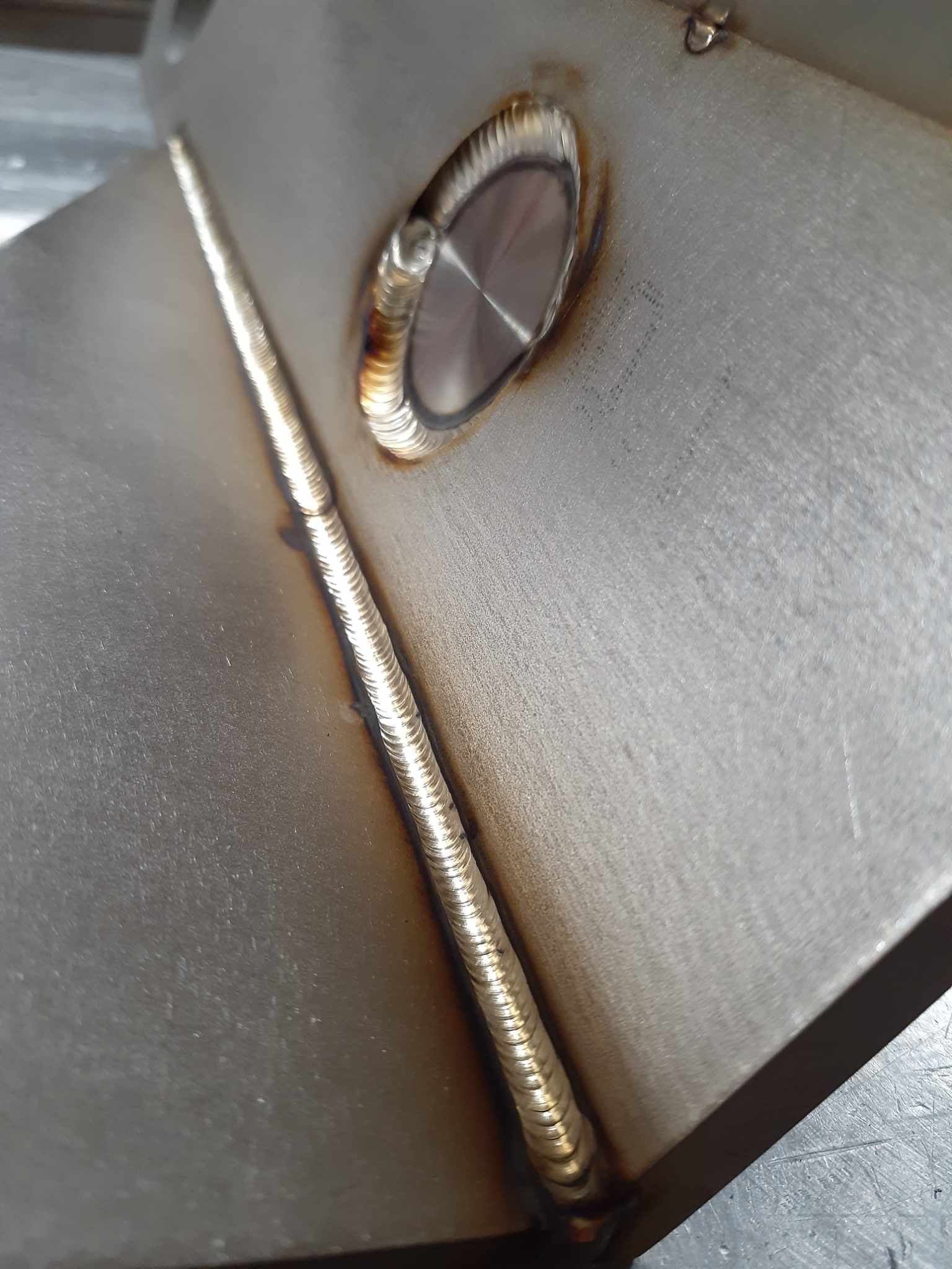
Tig Welding
Gas tungsten arc welding also known as tungsten inert gas welding (GTAW/TIG) is an arc welding process that uses a non-consumable tungsten electrode to produce the weld. The weld area and electrode are protected from atmospheric contamination by an inert shielding gas (argon or helium).
A filler metal is normally used, though some welds, known as "fusion welds" do not require it.
The process grants the operator greater control over the weld than competing processes allowing stronger, higher-quality welds. However, TIG welding is comparatively more complex and difficult to master, and furthermore, it is significantly slower than most other welding techniques.
TIG welding is most commonly used to weld thin sections of stainless steel and non-ferrous metals such as aluminium, magnesium, and copper alloys. (pick another metal instead of magnesium)
| Our Press Brake Checklist | ||
|---|---|---|
| ✓ High Accuracy & Repeatablity | ✓ Features Close to Bendline | ✓ Small Radius |
| ✓ Prototypes & Production Runs | ✓ Short Flange Lengths | ✓ Large Radius |
| ✓ Sheet, Bar, Perforated, Textured, Expanded, Diamond* | ✓ Return Flanges | ✓ Incremental Forming |
| ✓ 6" Tall 4-Sided Box | ✓ Cross Brake | ✓ Cones & Transitions |
| ✓ Up to 1/2" Thick* | ✓ Hemming | ✓ Transitions |
| ✓ Up to 13' Long* | ✓ Staged Setups | ✓ Offsets & Joggles |
| ✓ SS, CRS, AL, Copper, Inconel | ✓ Tough To Gauge |
Mig Welding
Gas metal arc welding or metal inert gas (GMAW/MIG) is a welding process in which an electric arc forms between a consumable MIG wire electrode and the workpiece metal, which heats the workpiece metal, causing them to fuse (melt and join). Along with the wire electrode, a shielding gas feeds through the welding gun, which shields the process from atmospheric contamination.
The process can be semi-automatic or automatic. A constant voltage, direct current power source is most commonly used with GMAW, but constant current systems, as well as alternating current, can be used. There are four primary methods of metal transfer in GMAW, called globular, short-circuiting, spray, and pulsed-spray, each of which has distinct properties and corresponding advantages and limitations.
Originally developed in the 1940s for welding aluminium and other non-ferrous materials, GMAW was soon applied to steels because it provided faster welding time compared to other welding processes. The cost of inert gas limited its use in steels until several years later, when the use of semi-inert gases such as carbon dioxide became common.
Today, GMAW is the most common industrial welding process, preferred for its versatility, speed, and the relative ease of the process.
| Our Press Brake Checklist | ||
|---|---|---|
| ✓ High Accuracy & Repeatablity | ✓ Features Close to Bendline | ✓ Small Radius |
| ✓ Prototypes & Production Runs | ✓ Short Flange Lengths | ✓ Large Radius |
| ✓ Sheet, Bar, Perforated, Textured, Expanded, Diamond* | ✓ Return Flanges | ✓ Incremental Forming |
| ✓ 6" Tall 4-Sided Box | ✓ Cross Brake | ✓ Cones & Transitions |
| ✓ Up to 1/2" Thick* | ✓ Hemming | ✓ Transitions |
| ✓ Up to 13' Long* | ✓ Staged Setups | ✓ Offsets & Joggles |
| ✓ SS, CRS, AL, Copper, Inconel |
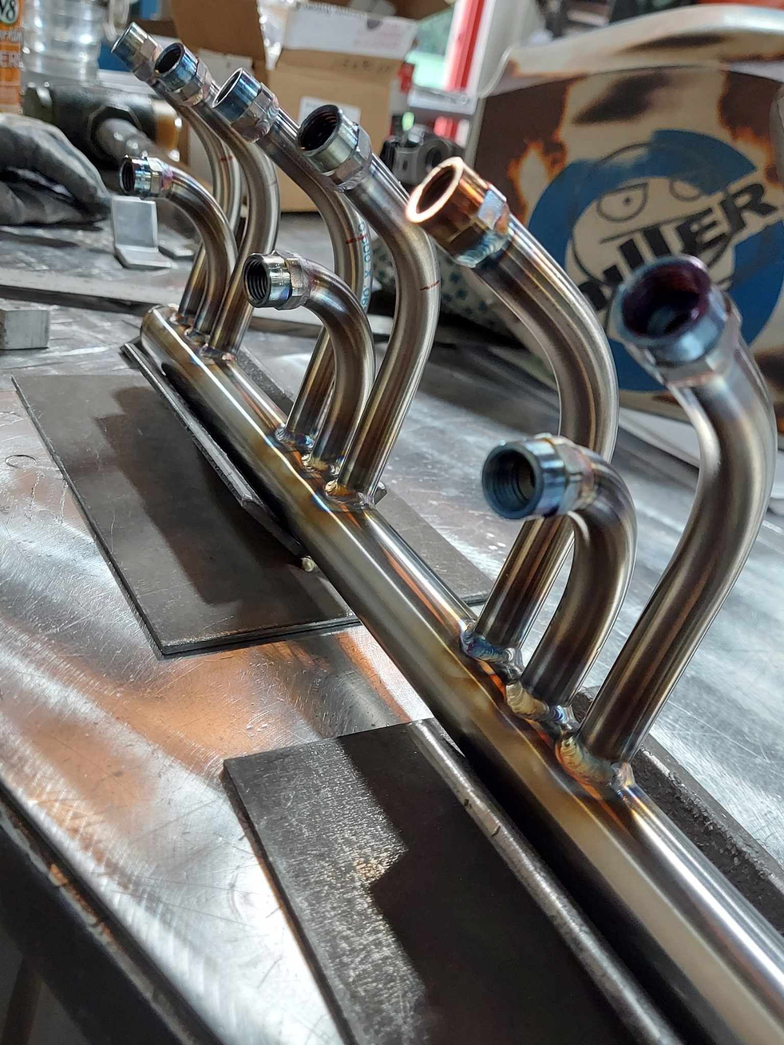
Orbital Welding
Orbital welding is a specialized area of welding whereby the arc is rotated mechanically through 360° (180 degrees in double up welding) around a static workpiece, an object such as a pipe, in a continuous process. This method and technology was developed to address the issue of operator error in manual gas tungsten arc welding (GTAW) applications requiring precision tube and pipe welding. To ensure high-quality repeatable welds a more stringent weld criteria was set by the ASME.
In orbital welding, an automated computer-controlled process runs with little intervention from the operator. and the relative ease of the process. Note that a welding operator is always monitoring and controlling the process. In an ideal situation, all welding parameters would be fully programmed before welding is started. In practice, however, the presence of variable constraints means that it is often necessary for the welder to make corrective interventions and create custom programs for the application.
A successful orbital weld is 100% automatic and repeatable as long as the operator monitors variables and performs periodic inspections of the weld seam for complete penetration of the weld. Noticing that a variable has changed during the welding process is a necessary skill for orbital welding technicians and operators that can be easily missed. Training and experience are required for an operator to be successful at consistently producing acceptable, repeatable, high-precision welds that meet today's standards.
Several critical variables can affect the success of an orbital weld. These include using the proper weld program in the orbital welding power supply or controller to match the settings to the pipe size, wall thickness, and tube material. Other key factors include the pipe preparation and face, the correct positioning of the weld head on the tube, and the amount of oxygen present during the welding process. Maintenance of the weld head often becomes a factor in the repeatability of successful welds.
Successful orbital welding is also dependent upon using high quality tubing material. Typically only 316L stainless steel tubing (not pipe) and fittings are used for automatic orbital welding and are obtained from a number of specialty manufacturers. The weld quality depends upon having a reasonably clean source of Argon for backing and shielding gas. Minimum purity would be 99.995% for typical industrial applications. For some applications it is necessary to use ultra high purity argon, 99.9998% purity and such applications requires the use of all high purity purge equipment (valves, regulators and flow control). Typically, no rubber components can be used for purge gas apparatus since the rubber absorbs and releases moisture and oxygen into the argon stream. Moisture and oxygen (in Argon) are contaminants detrimental to a successful automatic orbital weld.
Orbital welding is more commonly performed on tubing than on pipe for several reasons, most important being that the production of tubing yields very consistent outside diameters which is critical to proper fit up in the weld head.
Automatic Orbital GTA welding has become the standard joining method for high integrity gas and liquid systems used in the Semiconductor and Pharmaceutical manufacturing industries. These systems are rated for extreme purity and leak tight integrity. An entire specialty industry supplying valves, fittings, regulators, gauges and other components for orbital welding and use in high purity applications has developed since the mid 1980s. For tube welding in high purity applications only a fully enclosed weld head may be used.
| Our Press Brake Checklist | ||
|---|---|---|
| ✓ High Accuracy & Repeatablity | ✓ Features Close to Bendline | ✓ Small Radius |
| ✓ Prototypes & Production Runs | ✓ Short Flange Lengths | ✓ Large Radius |
| ✓ Sheet, Bar, Perforated, Textured, Expanded, Diamond* | ✓ Return Flanges | ✓ Incremental Forming |
| ✓ 6" Tall 4-Sided Box | ✓ Cross Brake | ✓ Cones & Transitions |
| ✓ Up to 1/2" Thick* | ✓ Hemming | ✓ Transitions |
| ✓ Up to 13' Long* | ✓ Staged Setups | ✓ Offsets & Joggles |
| ✓ SS, CRS, AL, Copper, Inconel | ✓ Tough To Gauge |
Resistance Welding
Electric resistance welding (ERW) is a welding process in which metal parts in contact are permanently joined by heating them with an electric current, melting the metal at the joint.
The electric current is supplied through the electrodes that also apply clamping pressure.
Electric resistance welding is widely used, for example, in manufacture of steel pipe and in assembly of bodies for automobiles.(change this to our industries)***
In general, resistance welding methods are efficient and cause little pollution, but their applications are limited to relatively thin materials.
Spot welding is a resistance welding method used to join two or more overlapping metal sheets, studs, projections, electrical wiring hangers, some heat exchanger fins, and some tubing. Usually power sources and welding equipment are sized to the specific thickness and material being welded together. The thickness is limited by the output of the welding power source and thus the equipment range due to the current required for each application. Care is taken to eliminate contaminants between the faying surfaces. Usually, two copper electrodes are simultaneously used to clamp the metal sheets together and to pass current through the sheets. When the current is passed through the electrodes to the sheets, heat is generated due to the higher electrical resistance where the surfaces contact each other. As the electrical resistance of the material causes a heat buildup in the work pieces between the copper electrodes, the rising temperature causes a rising resistance, and results in a molten pool contained most of the time between the electrodes. As the heat dissipates throughout the workpiece in less than a second (resistance welding time is generally programmed as a quantity of AC cycles or milliseconds) the molten or plastic state grows to meet the welding tips. When the current is stopped the copper tips cool the spot weld, causing the metal to solidify under pressure. The water cooled copper electrodes remove the surface heat quickly, accelerating the solidification of the metal, since copper is an excellent conductor. Resistance spot welding typically employs electrical power in the form of direct current, alternating current, medium frequency half-wave direct current, or high-frequency half wave direct current.
The advantages of the method include efficient energy use, limited workpiece deformation, high production rates, easy automation, and no required filler materials. When high strength in shear is needed, spot welding is used in preference to more costly mechanical fastening, such as riveting. While the shear strength of each weld is high, the fact that the weld spots do not form a continuous seam means that the overall strength is often significantly lower than with other welding methods, limiting the usefulness of the process.
In a fusion bond, either similar or dissimilar materials with similar grain structures are heated to the melting point (liquid state) of both. The subsequent cooling and combination of the materials forms a “nugget” alloy of the two materials with larger grain growth. Typically, high weld energies at either short or long weld times, depending on physical characteristics, are used to produce fusion bonds. The bonded materials usually exhibit excellent tensile, peel and shear strengths.
| Our Press Brake Checklist | ||
|---|---|---|
| ✓ High Accuracy & Repeatablity | ✓ Features Close to Bendline | ✓ Small Radius |
| ✓ Prototypes & Production Runs | ✓ Short Flange Lengths | ✓ Large Radius |
| ✓ Sheet, Bar, Perforated, Textured, Expanded, Diamond* | ✓ Return Flanges | ✓ Incremental Forming |
| ✓ 6" Tall 4-Sided Box | ✓ Cross Brake | ✓ Cones & Transitions |
| ✓ Up to 1/2" Thick* | ✓ Hemming | ✓ Transitions |
| ✓ Up to 13' Long* | ✓ Staged Setups | ✓ Offsets & Joggles |
| ✓ SS, CRS, AL, Copper, Inconel |
machines that fit every job
Modern and legacy tooling to support your needs
Niagara 50
$0/mo
16 gauge material in lengths up to 8 feet
Adaptable die sets for Punching & Emboss
Cincinnati 175
$29/mo
10 gauge material in lengths up to 13 feet
CNC Ram & Backgauge
Versatile & Cost efficient
AmaDA 187
$39/mo
1/4" material in lengths up to 13 feet
CNC 2 Axis Ram & 6 Axis Backgauge
High accuracy & repeatability
CNC Ram & 8 Axis Backgauge


Let’s talk about your project
Fill in the form or call to set up
a meeting at 610-868-0900.